Tuesday, 25 November 2014
Monday, 24 November 2014
In CATIA V5 when I select a face of a solid only its boundary gets highlighted. Can i highlight the whole face?
By default, only boundary will be highlighted.
To highlight the selected face, Select "Tools > Options > General > Display" on the menu bar
and then click on "Highlight faces and edges" and click ok.
To change the highlight color, select "Tools > Options > General >
Display > Visualization" on the menu bar and then change the color
of "Selected elements".
Questions on CATIA V5 Fundamentals .
CATIA V5
FUNDAMENTALS
CATIA is
commercial software suite developed by the French company Dassault
Systems and
marketed worldwide by IBM. Written in the C++ programming language. The
software was created in the late 1970s and early 1980s to develop Dassault's
Miragefighter jet, then was adopted in the aerospace, automotive, shipbuilding,
and other industries. Catia V5 features a parametric solid/surface-based
package which uses nurbs as the core surface representation and has several
workbenches that provide support. V5 can work with other applications,
including Enovia, Smarteam, and various CAE
Analysis applications.
1. Expand CATIA?
Computer Aided
Three Dimensional Interactive Applications.
2. Can I open solid works files in CATIA?
Sorry, you cannot
open Solid works files directly in CATIA. You can use Solid works to export
your solid works files into STP, IGS, or X_T format. CATIA can open those
files, but the history of modelling will be lost.
3. Does CATIA works on UNIX platform?
Yes.
4. Is it possible to hide specification tree?
Yes, with help of F3 button, but the option in tool command
must be checked ok.
5. What are features?
A feature is the smallest building block that can be
modified individually. A model created in CATIA V5 is a combination of number
of individual features and each features is related to one another directly or indirectly.
If proper design intent is maintained while creating the model, then these
features automatically adjust their values to any change in their surroundings.
6.
What are the different types of documents in CATIA V5?
All files created using CAtTIA V5 are referred
to as documents.
The
common documents are:
1. A
part document (.CATPart)
2.
Sketcher document (.CATPart)
3.
Assembly document (.CATProduct)
4. A
drawing document (.CATDrawing )
5.
Surface Design (.CATPart)
6.
GSA (.CATAnalisis)
7. NC
(.CATProcess)
8.
Material (.CATMaterial)
9.
Shape (.CATShape)
7. How
can I hide an element while creating complex designs?
Show
mode help us to see all components
presently opened.
You can hide an element by transferring it to the no show space for time being.
Click on Hide/Show icon.For the hidden elements,their icons will be in shade.
Elements are now hidden and the screen appears as below.
8. How can i activate the
auto-update mode in CATIA V5?
Select “Tools > Options > Mechanical design >assembly design > general > update > automatic “
Select “Tools > Options > Mechanical design >assembly design > general > update > automatic “
Saturday, 25 October 2014
. How to work with mouse in CATIA V5 ?
1.
Panning - to move the model on a plane parallel to the screen.
Click
and hold the middle mouse button, then drag the mouse.
2.
Rotating - to rotate the model around a point.
Click
and hold the middle mouse button and the right button, then drag the mouse.
3.
Zooming in/out - to increase or decrease the size of the model.
Click
and hold the middle button,
then click ONCE and release the right button, then drag the mouse up or down.
How to reset toolbar when disappear from Catia V5 work bench. Why it happens?
Every toolbar has a "X" button on its upper right corner. If you select it, the toolbar will be closed.
If you Select
“View > Toolbars”(your selection)
The
list of current toolbars will be displayed. Currently visible toolbars are indicated
by a tick symbol to the left of the toolbar name.From the list, click the toolbar you want to view or hide.
You
can detach toolbars from the application window border by dragging the double
line to the left of the toolbar. You can drag the toolbar anywhere around the
screen, then dock the toolbar in the same or in another location by dragging it
onto the application window border.
To
restore the original positions of the toolbar on the current workbench,
Select “View>Customize>Toolbars>Restore
position”.
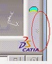
Sometimes the toolbar may be hidden at the lower
right corner of the window. If you see a double-arrow icon at the corner, it
means more toolbar are available. Drag out the other toolbar so that more can
be seen.
Subscribe to:
Comments (Atom)


